|
|
|
CHRISTCHURCH AND DISTRICT MODEL FLYING CLUB
|
 |
|
Profile (No-Cal) Auster for indoor flying, by Mike Roach
|
|
|
PART 1
Ive built a number of complicated balsa built-up and Depron models for indoor scale and fancied something a little easier. But it still had to look like a real aeroplane and be suitable for my Falcon RC set-up. 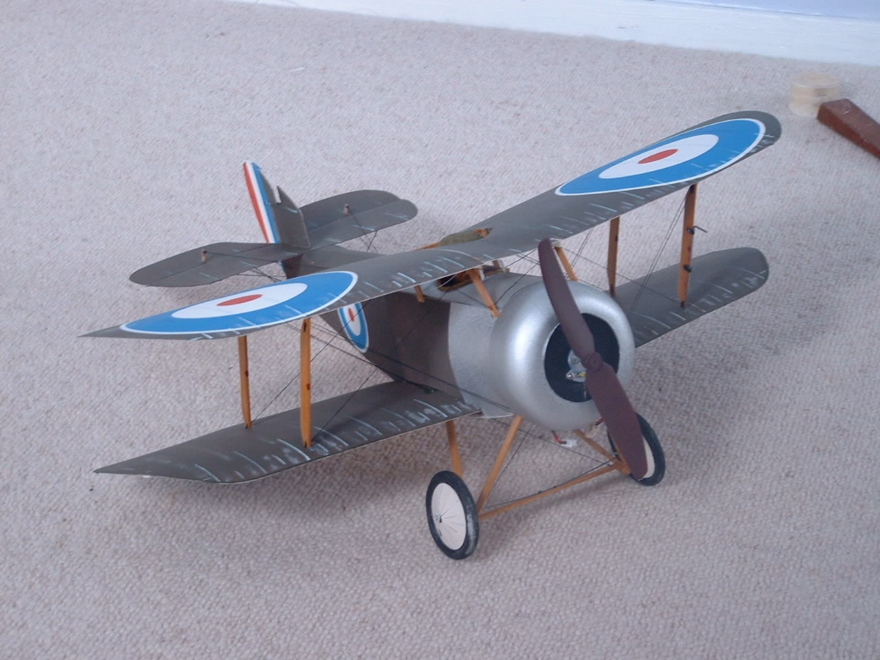 The little Sopwith in the picture is 15 span with a PU05 motor and with a freshly charged single cell lipo has enough power to cruise on 1/3rd throttle, so a high-wing monoplane should be able to span 30. The maximum flying weight for these little planes is 1.5oz, of which 0.75oz is the RC hardware and the motor: it doesnt take much calculation to see that the airframe has to be quite light! I have no doubt that a careful modeller could make a fully scaled version of the Auster with an ounce of balsa and tissue, but as I said, I needed a simple project! I enlarged my internet copy of the Derek Buckmaster plan by 130% and, with the keep it simple, stupid! legend pasted on the wall, got out my stock of 1/16th square balsa. . The little Sopwith in the picture is 15 span with a PU05 motor and with a freshly charged single cell lipo has enough power to cruise on 1/3rd throttle, so a high-wing monoplane should be able to span 30. The maximum flying weight for these little planes is 1.5oz, of which 0.75oz is the RC hardware and the motor: it doesnt take much calculation to see that the airframe has to be quite light! I have no doubt that a careful modeller could make a fully scaled version of the Auster with an ounce of balsa and tissue, but as I said, I needed a simple project! I enlarged my internet copy of the Derek Buckmaster plan by 130% and, with the keep it simple, stupid! legend pasted on the wall, got out my stock of 1/16th square balsa. .
Derek is a prolific designer of free-flight models of Australian-built aircraft. His website has about 25 superbly drawn plans, all free PDF downloads. Go and see at http://mywebpage.netscape.com/dbdesignbureau/ Back to Top |
|
|
PART 2
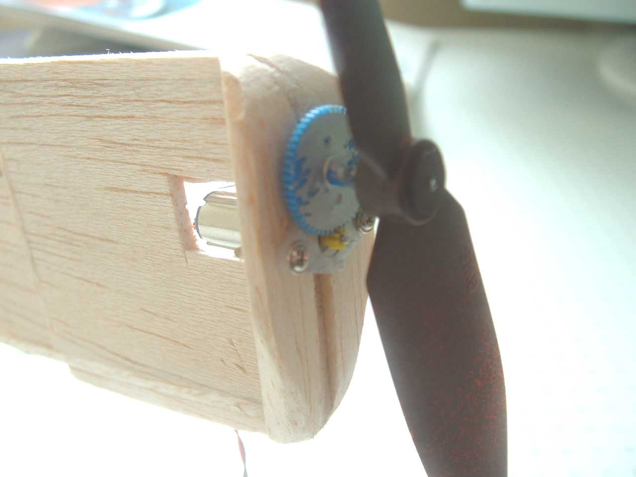
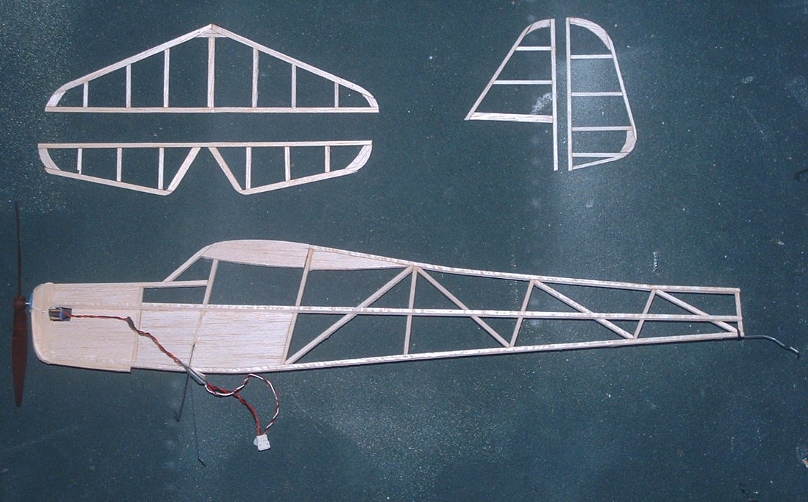
The fuselage went together very quickly, mainly from medium 1/8 sheet stripped to 1/8 square with a steel rule and sharp knife. The front section was filled with 1/8th and the flight pack mount area with 1/16th sheet. The motor is a Falcon PU05 which, its claimed, gives 20 grams of thrust from a 1 cell Lipo. I already had the SC and gear in the spares box so made a profile mount from some spare triangular section balsa and screwed in the motor. It all suddenly felt very heavy!
The tail was made from 1/16 x 3/32 strip and took about 20 minutes.
|
|
|
|
|
|
|
 |
 |
|
|
|
|
Part 3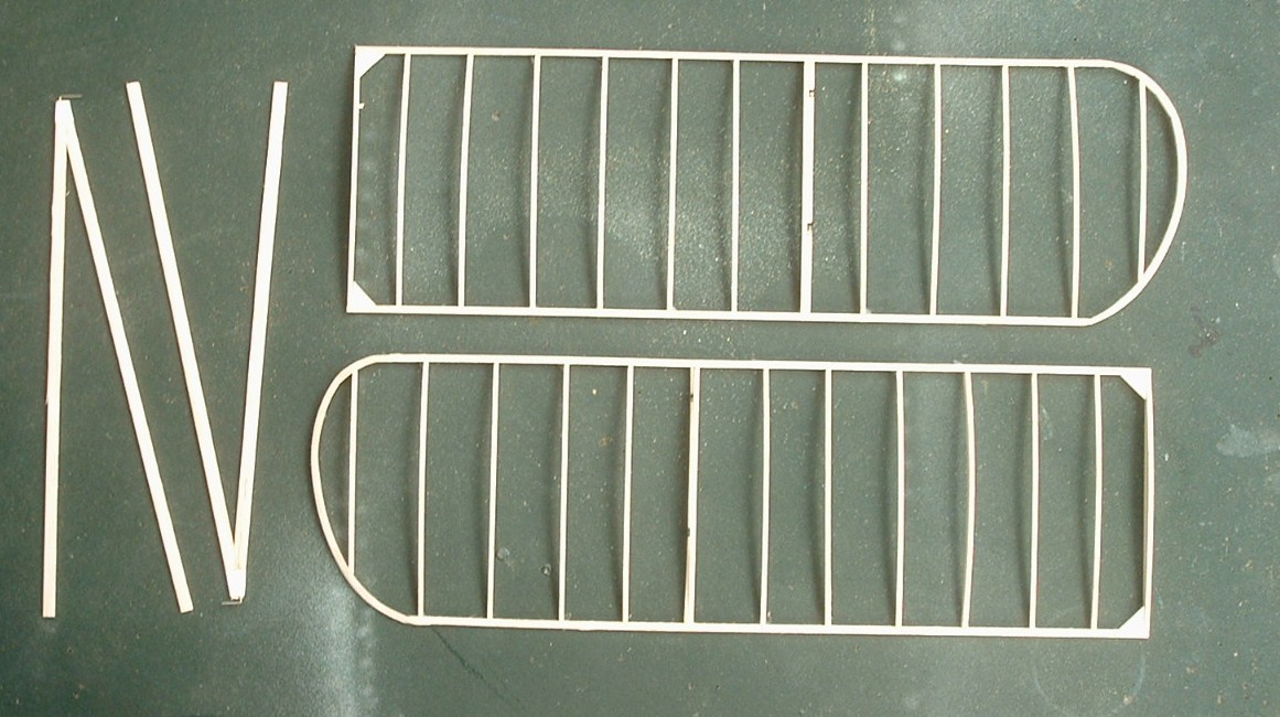
The wings are built using the traditional sliced rib method, which is a very easy way of making a light structure, but which needs care at the covering stage. The LE and TE are from 1/8 square, pinned down over some clingfilm. The ribs are sliced from medium 1/16 sheet then cyanoed into position. Cutting a section of the sheet to a fraction over the exact chord, then cutting the ribs from it makes easy work of fitting the ribs: they just spring into place and are held there while the glue sets. The end rib is the only solid one.
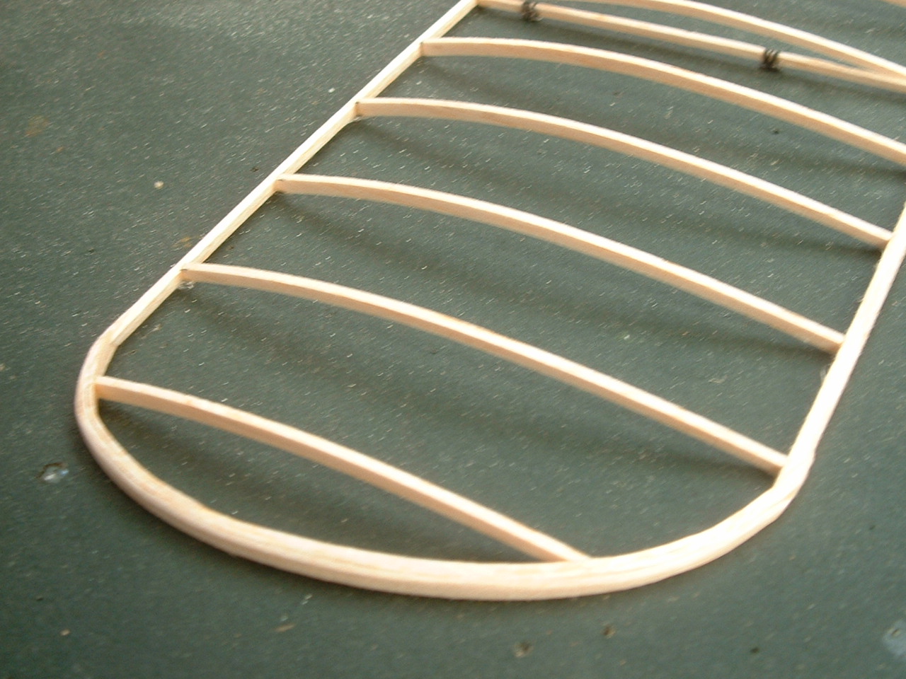 As usual I laminated the wingtips, using 3 layers of 1/32x1/8 soft - overkill really as 2 layers would have done. For models of this size.laminating is very easy. Just trim the LE and TE to the angle that the tip makes and put a row of pins round the inside of the tip shape. Dampen all the laminations and pin the first in place round the pins, glueing it to the LE and TE. The second lamination can be glued in place straight away (using cyano make very quick work of this - but whip the pins out from between them quickly) followed by the third. Leave for 5 minutes, then take off the board, pick off the clingfilm and sand smooth. The tips are very easy to sand as the grain is constant throughout. . As usual I laminated the wingtips, using 3 layers of 1/32x1/8 soft - overkill really as 2 layers would have done. For models of this size.laminating is very easy. Just trim the LE and TE to the angle that the tip makes and put a row of pins round the inside of the tip shape. Dampen all the laminations and pin the first in place round the pins, glueing it to the LE and TE. The second lamination can be glued in place straight away (using cyano make very quick work of this - but whip the pins out from between them quickly) followed by the third. Leave for 5 minutes, then take off the board, pick off the clingfilm and sand smooth. The tips are very easy to sand as the grain is constant throughout. .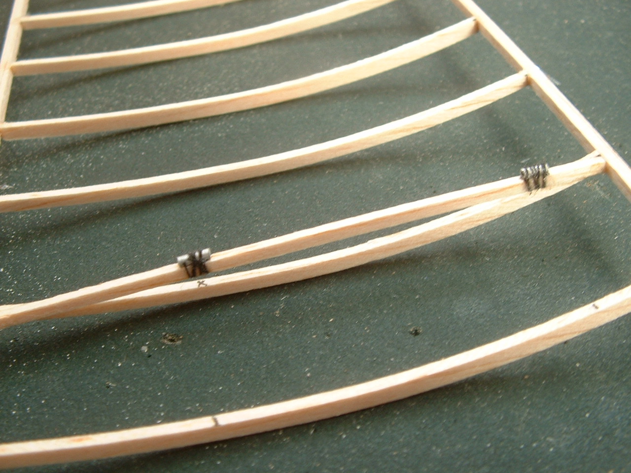
One of the ribs has to have a couple of fittings inserted to make the strut attachments. I just used a strip of 1/16 square and bound short lengths of alloy tube at the fore and aft points. The strut ends will have some soft wire inserted which can be fed through the tubes then turned back on itself to secure them.
Having made the wings, there were still the struts and the various fixing points on the fuselage to sort out. Even with a one-piece model with load-bearing struts, you still need some sort of attachement to stop everything falling apart in the air! The wires just push into the wing end ribs. The struts were easy, just 1/16th strips cut to shape and cyanoed together. I remember the best tip I ever had about modelling came from Clive Spencer, the last Chairman. He said - of using cyano - a spot of glue on one part and lick the other, then join them together. It really does work and accellerates the bond. Especially if you lick the glued part by mistake! The wire fixings at the strut ends are not very good and will be replaced with soft wire (florists wire) which can be bent back on itself to secure the struts. Covering next, and a new way to stick tissue to the airframe.
|
|
|
|
PART 4
Only one side of the surfaces is covered. Covering with tissue in the traditional way using dope and thinners is the lightest but most fiddly method of preventing the air passing through the structure. You could try Litespan or Airspan for a slight weight penalty. Or you could have a go with tissue using the method I invented for this project (it cant possibly be the first time its been tried) of using Balsaloc to attach the tissue.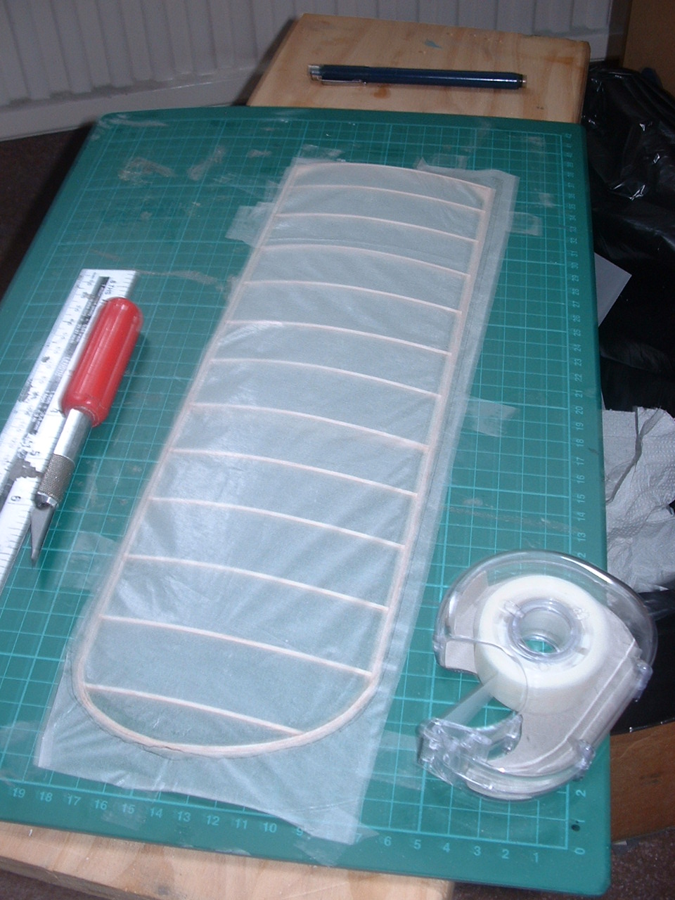
I used Jap lightweight tissue, but Modelspan will be fine. Lay the part to be covered over the sheet of tissue and mark 1/4 outside the outline with a soft pencil. Remove the part and paint a thin strip of Balsaloc onto the tissue, up to the pencil line, and sufficiently wide to overlap the edges of the part. Allow the Balsaloc to dry then cut out the tissue just inside the pencil line. Lay the tissue over the part and tape it down tightly as you see in the picture so that all the wrinkles are removed (but not so tightly that it stretches and will warp the part).
Now, using an iron on Nylon, iron down the tissue to the outlines of the part, stretching the tissue slightly to remove any wrinkles.
The next stage removes excess tissue from the edges. Using a steel rule and a sharp blade, trim off the tissue to within 1/8 of the part (curved sections have to be done by hand), then seal these edges - which already have glue on them - round the edges of the part. Simple! You cant shrink the tissue, so mist some white Tamiya Acrylic over the tissue to give the model a bit of body and add transfers, decoration etc.
|
|
|
|
PART 5 Fitting out
You have done the decoration already, havent you?
There is very little to do in terms of assembly. The tailplane glues directly to the fuselage (I used a strip of 1/16th sq to make a key for the glue) and as you can see from the first photo, the fin has a sternpost to help get the alignment right. I used strips of invisible tape to make the hinges.
The easiest way to assemble the wings to the fuselage is to block the latter upside down, about 1/2 off the board, which gets the dihedral about right. Then slide the wings onto the locating pegs and spot glue. The strut ends must have short lengths of florists wire attached (I used heat-shrink film to do this, but the traditional way is to bind them on with thread). The fuselage ends are fixed into the alloy tubes and the wing ends trimmed to length and more florists wire attached. These ends are then slid into the wing tubes and the incidence and dihedral tweaked using the soft wire to make slight adustments. The wire is then bent back on itself to secure the join.
Thats it!
The RC gear is just fitted where convenient, making sure that the model balances at 1/3rd chord. The battery can be shifted around to make adjustments.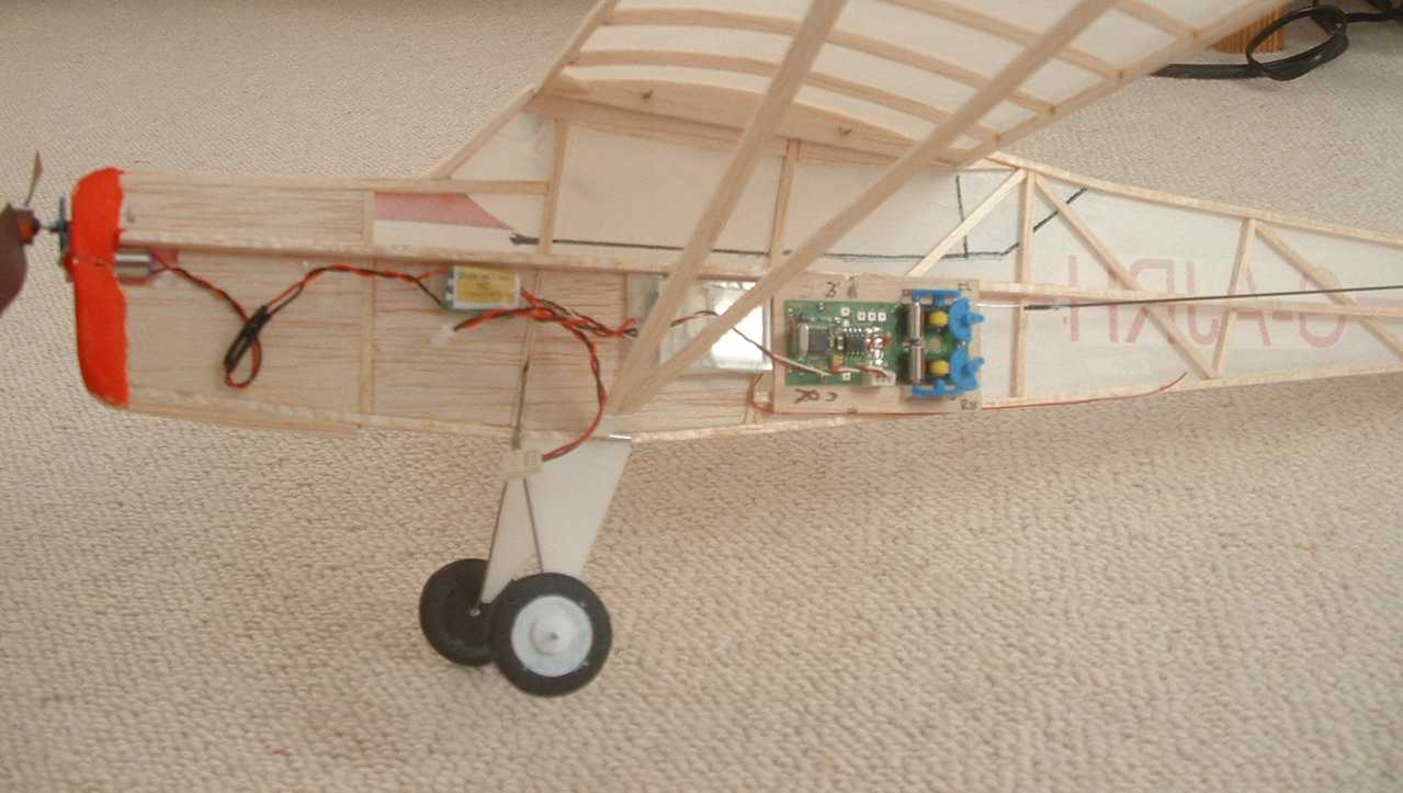
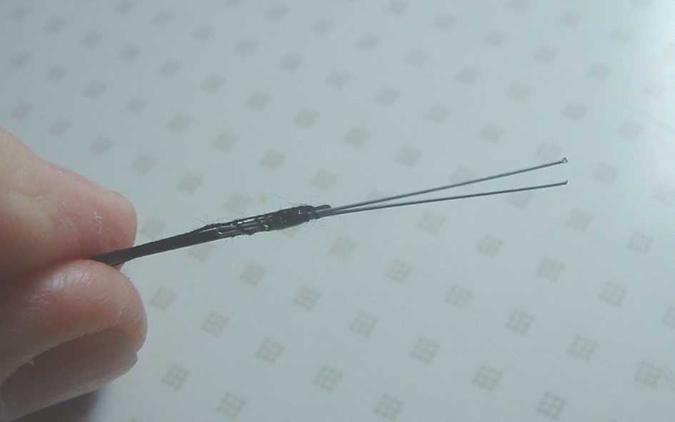
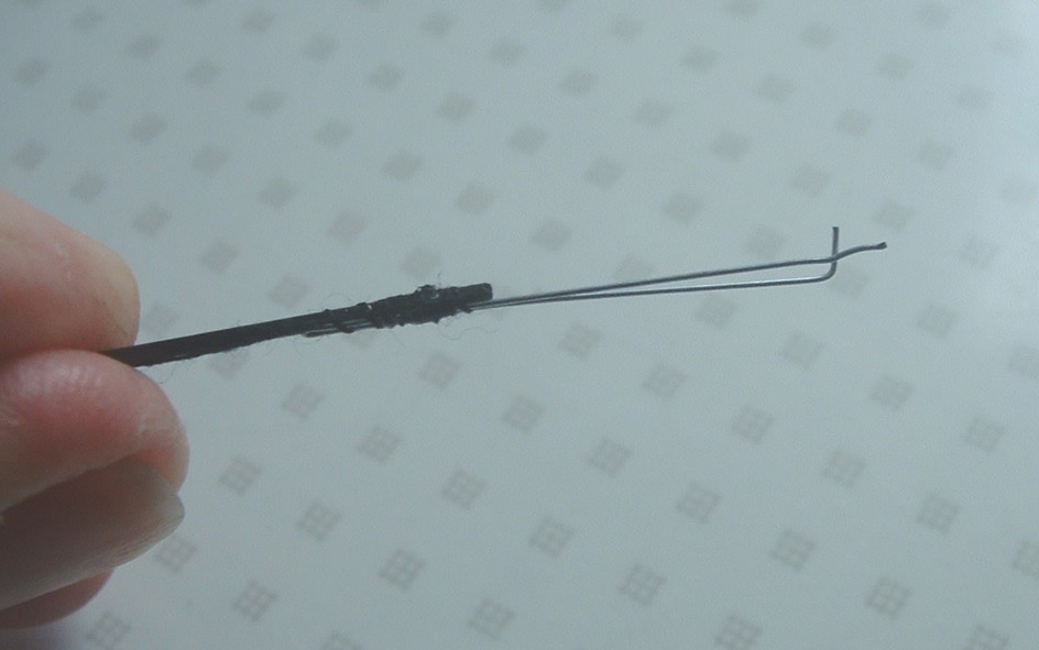
The controls are connected using 1mm CF rod with end fitting made from more florists wire (FW). The servo ends have Z bend connectors and the other ends have a keeper arrangement shown in the photos. A length of FW is doubled and bound to the end of the rod. One end is then bent to a right angle, and when this is located in the control horn, the other forms the keeper. It appears flimsy in the hands, but is more than strong enough on the model. Keep the Z bend nice and short, otherwise it will foul the chassis of the Falcon servo and stall the movement.
  |
|
|
|
PART 6 Flying
Theres always a certain amount of trepidation involved in flying a new model indoors, even one that can be made in a mere couple of days. I took the Auster to Calshot Velodrome one evening in December and, amid the flocks of Shock Fliers tried a first fight. Oops! She lifted for the ceiling and I had to hold in all the down to get level flight. A quick landing and some adjustment and she flew nicely for a few circuits - enough to show great potential, but dived hard for the ground when the throttle was closed. Back home, 5 degrees of downthrust was specified, with a return to the neutral elevator setting.
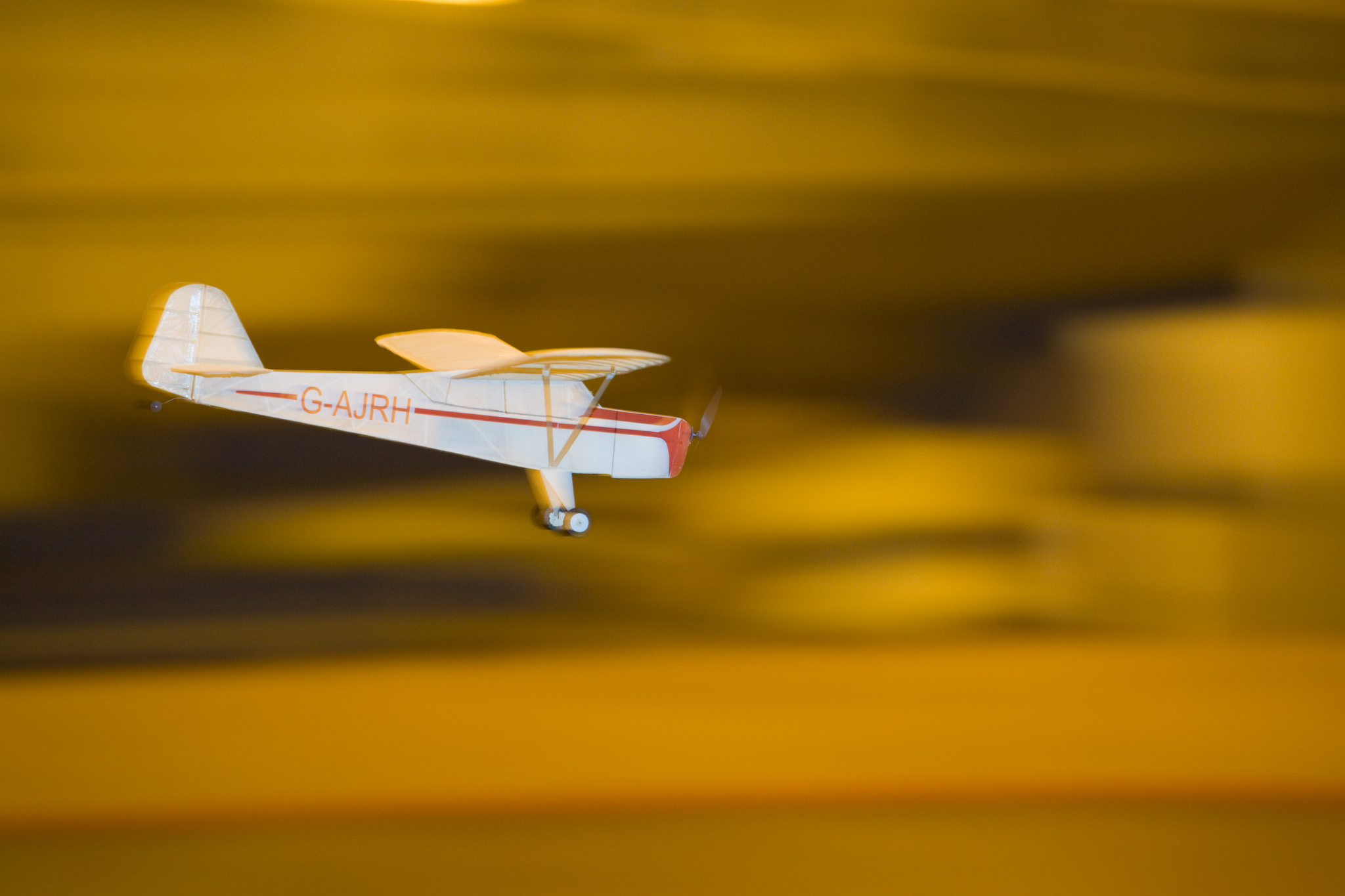 Photo by Jon Roach: www.fourt4.com Photo by Jon Roach: www.fourt4.com
The next trip out was at the invitation of John Thompson, the Chairman of Southampton MAC, and was also at Calshot, my favourite venue. Trevor Hewson and I made the journey, were welcomed by mince pies and mulled wine and in a haze of goodwill and alcohol, I tried another flight. This time the fight pattern was much better and the little plane could be trimmed to take off, fly round and even land with only throttle control. She really is a delight to fly and shows the potential for other models in a similar style: any of the high wing light planes to the same span; any single bay biplane to about 24 span, a Spitfire to 26 span (ailerons would a little complication). Just enlarge a plan to the right size and build the profile structure over it.
Specifications:
Span 30, flying weight 1.25oz, Falcon PU05 motor and prop, Falcon 1-cell speed controller and 1-cell 150-mAh battery, Falcon Breeze-Block RX and servo assembly. Rudder, elevator and throttle control. Airframe from 1/8 and 1/16th balsa strip. Covering Jap light tissue, not shrunk but very lightly sprayed white. Transfer decorations.
And remember any changes you make will only add weight!
|
|
|
PS
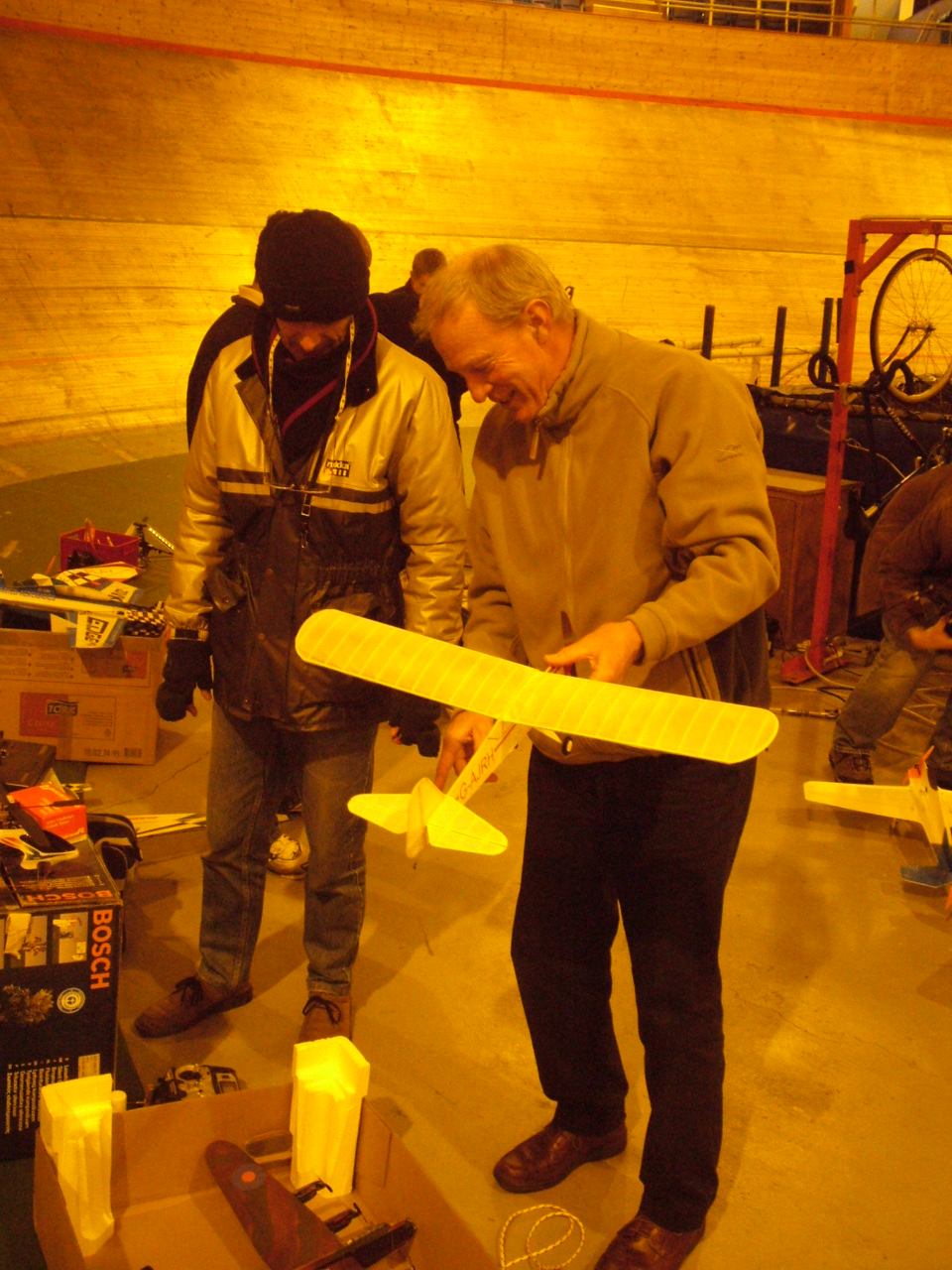
Trevor and me at Calshot in December 2006. The Auster had just flown successfully - hence the big grin!
Photo by Alan Bond
PPS
The Auster is featured in the May issue of Aviation Modeller International (www.modelactivitypress.com) and the April issue of RC Micro World Online magazine (www.cloud9rc.com)
|
|
|
|