|
|
||||||||||||
|
Christchurch and District Model Flying Club |
|
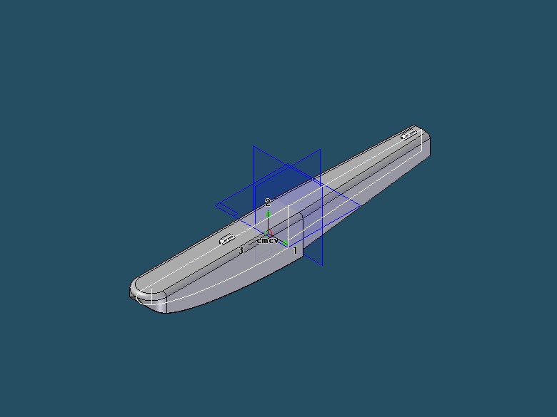
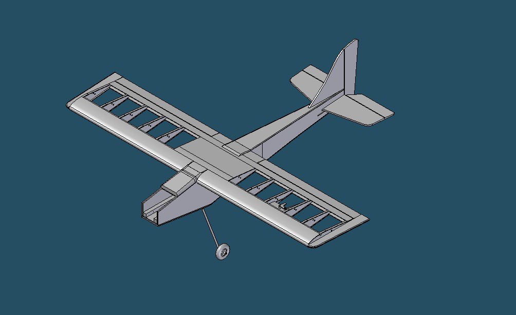
My use of 3D CAD for aeromodelling 3D CAD has been around since the 1970s and in the beginning was only affordable and practical for very large companies with equally large main frame computers. Fast forward to the 1990s and the availability of good desk top computers, steriolithography and plotters and 3D CAD began to be used by medium and small manufacturing companies. By the turn of the century 3D CAD was necessary and commonplace in product manufacturers of all sizes, and with the emerging internet even singletons working from home with 3D CAD could be integrated into the design activity of product manufacturers. My CAD dates back to the turn of the century and now runs on a laptop getting on for 10 years old. It is out of date now but hopefully will “see me out” in my hobby. 3D CAD systems create 3 types of files, “part” files, “assembly” files and “draft” files. Work begins with the modelling of all components in a design in “part” files. The components are modelled in 3D and real size. There is generally a facility to input data such as density so that the CAD can output data including volume, weight and C of G. for each part.
Part files can be used for rapid prototyping and 3D printing. Components/Parts can then be brought together in “Assemblies”. The parts will be mated and aligned in exactly the same way as when they actually exist. The CAD system can output data including the total accumulated weight and C of G of the assembly.
Assemblies or Sub Assembles can be combined again mating and aligning in the same manner as when they are real. It is at this stage that changes can be made to the disposition of parts – in the case of model aircraft- this might involve moving the location of the battery, servos or receiver to get the overall C of G somewhere near the desired position at the centre of lift. Once the General Assembly has been established, the draft files can be created for the component parts and assemblies. Once the drawings have been printed it will be onwards to the building board.
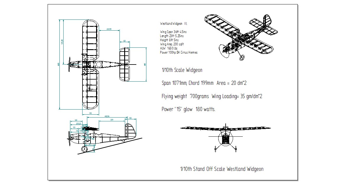
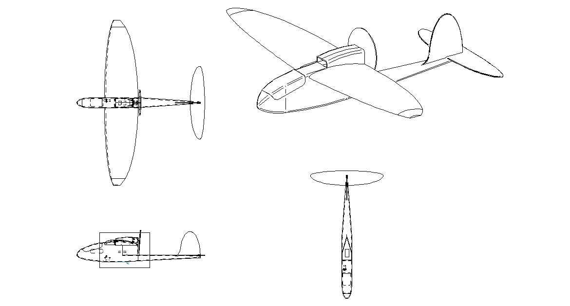
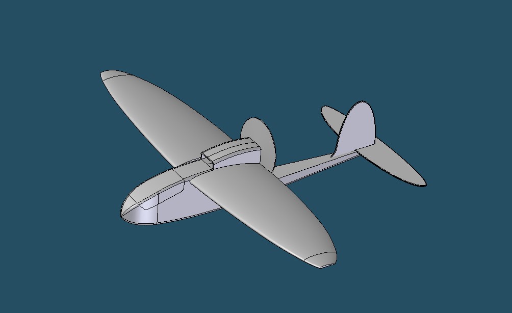
Since I retired 10+ years ago, I have continued to design models on my CAD, I appreciate it is not a typical approach, but I find it “fun” to build my model twice – once on the computer and once on the building board. It doesn’t save time, but it does save on material because there is no cutting and modifying a newly build model. The accompanying pictures show some of the models I have designed, built and flown. The most recent is the “Elliptical Pusher” which flew at Winn Green last Autumn.
Adrian |
| [Home] [Chairman's Chatter] [Tailpiece] [Cold War Worrier] [Working with CAD] [Dry Transfer] [End of the Line] [The Archive] [Fly Diary] |
