|
|
||||||||||||||||
|
christchurch and district model flying club |
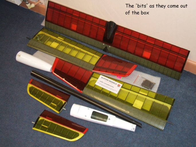
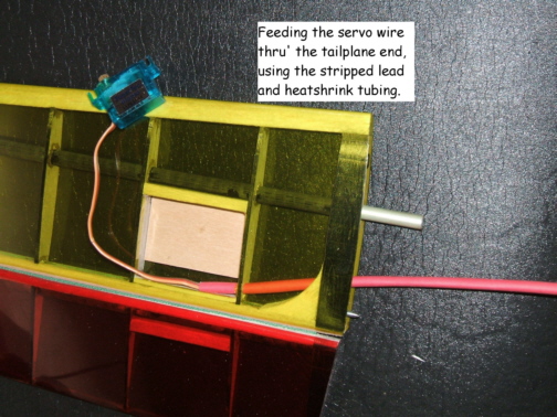
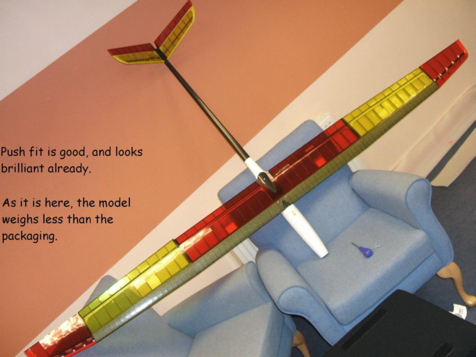
This isnt meant to be a definitive paper on the How To or Not, of the Bingo, but my point of view. After seeing the kit reviewed in the October 2006 issue of Q&EFI by Brian Sharp, I set my mind to the idea that it was a Must Have for me, so when the funds were available, I gave a call to Stan Rose of Elston Models, and a few days later was the proud possessor of a large box of foam chips, Oh, and some bits of stuff that would become a rather nice thermal electric glider. One thing extra I did order was the glider nose to compliment the electric, as I hope to set up the model for both, perhaps even on the one memory. What you get, is as the review says, a lot of lovely finished bits of carbon and Kevlar in the shape of 8 extremely light parts of a model. After the parts were removed, they took up so little room, you hardly noticed the difference to the level of the foam chips left in the box. So, to work. There are very little in the way of construction notes with the kit, more a set of surface travel recommendations, and the suggested motor/gearbox combo. Curiously, there are no suggested prop sizes, so Ill give Stan a ring on the morrow, and see what he has to say. I also want to see how the Bingo would go on Lipos. First things first. Over to Ch4 and part with more hard earned, to obtain the necessary to waggle the flappy bits. I got enough HS81 MG, and a couple of Saturn S4 digital servos for the ruddervators. After removing the covering from the under side of the servo hole, I came to the 1st little thing to negotiate. There isnt anything to attach the servo to. A quick rummage through the offcut box found enough 1/16 ply to make a couple of plates for the servos to be glued to, but dont forget to run the servo leads through the holes in the root of the tailplanes. I found the only way, without cutting the plug off, was to carefully remove the plug, one pin at a time and insert the wires into a length of heatshrink, then feed the tube through to the root. I expect to recover the open hole with some low temp covering, if I can find some leftovers. I assembled the tail tube to the fuz and put the wings and tail pieces in place. After Very carefully setting the wing horizontally, I eyed the tailplanes to check they were square to the wings. Marking the line-up, I offset the tail a small amount each way to see if it looked any better. This took 20 mins of going away and coming back, so that I was as sure as I could be, that I wasnt going to create a beast with a twisted tail. The 1st job Monday will be to set it out again, and check before applying glue to the tail boom to fuz join. O.K. So after breakfast, I set the fuz and tail tube up and checked for true, again. Satisfied that I couldnt get the two parts any more true without NASA technology or a second opinion, I set to the task of gluing these parts together. I put the 30min resin in a sink of hot water while I cleaned and de-greased the mating surfaces. A tip I was given, is to prepare the carbon, after gently keying the surface , by swiping with Acetone. So, I pinched the wifeys nail polish remover and got to it. Another useful idea is to wrap the joint in masking tape, once youre sure of alignment, and make a mark, (or two), across the join, so that you can quickly re-align the two parts after applying epoxy. Cutting the masking tape at the join means that you have a safe surface if you get any resin over the edges of the join. You will probably still have to wipe some excess away, but it will be easier to clean the finished joined fuz. While the glue was drying, I got on with the task of horns for the ruddervators. These were cut off horns from spare servo horns, as the supplied would have made a huge hole where I didnt want it. 5 minute epoxy for these, dont want them coming out. I did my usual bent wire/ soldered wire-spring-connector thing. If I need any adjustment later, I can adjust on the sub-trim or re-solder the connectors. I was lucky with the servo connectors for the tailplanes. The leads in the fuz from the receiver exit the fuz at preformed holes in the rear end, inline with connector sized holes in the tailpanes, so after feeding the leads into the fuz with connectors on, I fed the loose ends through the holes and added pins and connectors. When the two are coupled, the connectors fit into the ends of the tailplanes and butt against the first rib. I know that theyll not disconnect in flight, and the fit of the tailplane halves is so snug that a simple bit of tape will hold them in place. Funny thing is that when I first got the kit, I assembled the tail tube upside down. Thankfully I found out before gluing the two parts together.
After checking things were dry, and then checking the movement, I started on the ailerons. These went in the same way that the tailplane servos went in. The aileron horns are very posh alloy and brass widgets. I had to drill a 5mm hole to mount these in the ailerons. I supa-glued these, so I hope theyll hold, and if they dont, theyll re-glue easily enough. I did cut the alloy bits down a few millimetres. I didnt like the way they protruded through the top surface. There are two more fittings made from hexagonal brass, presumably for the flaps, but I will follow the magazine review and create some special horns for the flaps myself. Bad day at work today, so left it a while before going to the shed. Just as well, as while pulling leads for the servos through to the centre section, managed to damage two ribs. After finishing the positioning of the servos for the flaps, I called it quits tonight, before I did anymore harm. The long leads of the HS81s is a plus, as it means that I can get the flap lead ends into the centre section without having to cut and extend them. Didnt get to create the special horns for the flaps as per the magazine review, but its not a problem, until the glider nose arrives and sits on the bench for a month. I may not get to fly this under power until very late in the season. I should think this will miff one or two people who want to see the Bingo in the air almost as much as me. A little foot note here, is to say that all of the connectors are loose, meaning that they will not be fixed in either end of the wing or at the tail, so the connection is made, then fed back into the wind in/outboard section. This may surprise/ worry some, as Im relying on the tightness of the plugs to keep the lead together. The other thing is that there are after market items available called keepers, which fit to the lead either side of the plug, keeping it together. I may employ these in the finished version, as taping although good takes time and is a nuisance to undo. Did the extensions to the ailerons from the centre section to the outboard. The shroud on the male/female part of the connector, fits tightly into the hole from the centre section, so that when you push the outboard part in, it stays put. I will possibly open the aileron hole and have the connector disappearing into the outboard wing section instead. The choice of connection at the centre section opening has changed from my original idea, which was to use two MULTIPLEX 6 pin connectors. One for the ailerons, and one for the flaps. The servo leads from the flap servos reach the centre opening, so I re-plugged the leads and will make a colour coded connector from the receiver to the flaps. I will use a 6 pin connector for the ailerons after all, as it is perhaps the easiest to do. I have seen a six pin Futaba type connector for sale, but it was in Q&EFI some time ago, and I want to be ready for the glider nose arrival, not to spend the next two weeks looking through back issues of the magazine trying to find the one item, then wait six weeks for them to come from Germany. Called Stan Rose today about the prop mainly. Thanks for the natter , he told me 14x8-9. Could only find 14x9.5 today. It doesnt have to be a vertical climb out, so I may get away with the prop I bought for the Hoernia, that it didnt seem to like very much. Only an 11x10, but should get me airborne. Made a start on the programming today. By the way, if you buy an SPCM receiver, before taking the receiver back to the shop and complaining it doesnt work, re-set your tranny to transmit SPCM. It helps. Ruddervators set up, moving in the right direction and reduced throws. Nice. Managed to do a little and re-work the servo covers, while it was raining this morning. Lined them up, marked and cut them down. Then tacked the cut off piece with Zap-a-Gap and added some carbon toes across the back for joint strength. Taped over the servo wells with Diamond tape. Perfick. Programming re-started this afternoon, but hasnt gone according to plan. All this modern technology! For years Ive had the facility to be adventurous with the programming on my models, but never felt the need. Now when it matters I raise my hands, and hope to find some-one with more ability than me, familiar with JR. I have got some done, and the flaps work nicely with the different settings on the switch and I understand how to change the trim on them with the lever on the tranny, but I think must have something in the wrong hole. Something else just isnt moving when it should. Forgot to mention yesterday, that the glider nose will be in the country soon, and should be with me early next week. I had better get a shift on and start thinking about the hook, the mount and position relative to the Cof G. The glider nose arrived while I was away, so was waiting for me when I got into work this morning. Moulded to the same high standard as the rest of the moulded parts, and finished in a high gloss white, consisting of an outer sheath of carbon and Kevlar, and the inner sheath in white gel coated glassfibre. I think the inner sheath is supposed to be permanently attatched to the rest of the fuz, which is going to be a bit of a nuisance if I want to run the model in both guises, of power and glider. We shall see. The glider inner nose does have a shoulder in the moulding to, I assume, prevent it from disappearing into the rest of the fuz, and the sides are slightly flattened. The sheath outer is shaped in the same way as the motor nose, in that it has a top and bottom, with a double thick neck to it as it joins the rest of the fuz. In theory, I could cut the inner nose after gluing in, so that there is enough clearance for the motor nose to fit and it would provide a tray for the flight pack, which would be Lipos and have to be further forward for the CofG. If I use an extension lead for the speed controller, I could change to a receiver pack when glidering, and fit the right nose, with enough lead cast in and secured. Cast the lead for the nose to obtain the CofG at the suggested 71mm from the leading edge. I used the sheath without the inner nose, but it is likely that I will integrate the inner nose at some point in the future. I made a plate for the tow hook and used a piece of 2.5mm stainless steel bike spoke going spare for the hook, at the requisite 30deg forward of the CofG. The Maiden on the 25th of May will be off the bungey, though not at anywhere near full pull. O.K. For those of you not at the maiden . It wasnt all it was supposed to be. The wind was a little up, and not as calm as I might have wanted, but off things went. With the wind blowing so strong, the first flight should have told me enough was enough. Like a big kid with a shiney new toy I put the Bingo up again and this time not only did she fly backwards, but when it came to getting her down, it could have been worse. I landed out of the field which was fortunate as in the soft ground of the marsh, the nose went in well and the expected damage was much less. Such damage has been repaired and second opinions approve, but the opportunity to refly has not come about. I will have to get out to the slope sometime. So far as getting a gearbox of the requisite ratio, Ive had little to no luck so far. I think that I got a 3.44:1 in the end, (or close to), but the screws to mount the gearbox mounting plate to the motor are the wrong size, so I have to reshape some existing slotted pan heads or visit a local fastener supplier Ive used in the past. Eventually I will get the gearbox on the nose and fly powered. I expect to put the motor on the gear switch. I can use the throttle channel for the crow brakes, and have power on or off. After all, I bought the glider to compete in the thermal Electric glider summer comp, which has no-one else competing at the moment. |
|
[Home] [Chairman's Chatter] [Editorial] [Diary of a Flier] [Harry Spotters] [Ken's Seafox] [Cyril's Walrus] [Here we are...] [Ken's Piper] [Andrew's Alula] [Wild Things] [Reflections] [Andrew's Bingo] |