|
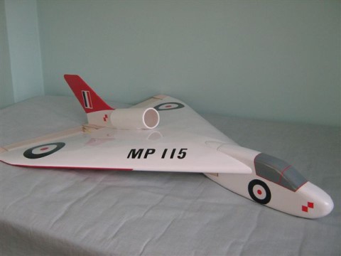
hP 115: A Slender Delta Glider and EDF Model
Designed by Martyn Pressnell
The inspiration to design and develop a delta-winged model originated from my own involvement with the Handley Page HP115 slender delta aircraft and was influenced by the earliest free-flight delta models that I witnessed, designed by Laurie Ellisback in the 1950’s.
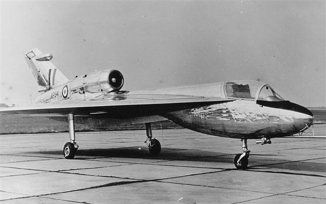
Handley Page HP 115
The HP115 was a slow speed research aircraft designed to investigate the handling characteristics of a very slender delta, flown in the evolution of Concorde. Initially conceived as a wooden glider to be towed aloft by a Canberra, it became a metal aircraft powered by a single Bristol Siddeley Viper ASV9 jet engine of 1,900 lb static thrust, mounted in a dorsal fairing at the rear of the fuselage. The AUW was 5,050 lb and it was capable of achieving an air speed of 300 mph. The aircraft itself resides in the RNAS Museum at Yeovilton alongside prototype Concorde 002.
The HP115, a small aircraft with fixed undercarriage, had a symmetrical, thin bi-convex aerofoil section, of 4% thickness with an interchangeable, sharp leading edge. Its wingspan was just 20 ft, and its overall length 42 ft from nose to jet pipe. The leading edge sweep was 74.7 degrees with an aspect ratio of only 0.92. This brought it into the regime where detached leading edge vortex flows were possible and expected, allowing the delta to achieve high angles of attack without stalling.
It was found to be generally comfortable in flight but with a few vices. One characteristic which became evident was the tendency to oscillate in roll at a high incidence. The airflow detaching itself from the sharp leading edges rolled up into strong vortices along the swept leading edges, being cast off towards the tips into the wake of the aircraft. It was found that this type of flow could become unstable, because any slight roll rate caused the vortex to strengthen on the descending wing resulting in more lift and then a reversal of the angle of bank. It was potentially uncomfortable flying but not necessarily dangerous. Concorde was fitted with roll and yaw dampers to avoid the phenomena.
The HP115 showed that its rolling motion was well damped at higher bank angles, so that the aircraft could be flown, steadily rocking about the sky at high incidence, or indeed the motion could be easily removed by the pilot’s counter control and lowering the nose. It was a very useful research aircraft, spending most of its life under test from the RAE airfield at Thurleigh in Bedfordshire. Its first flight was there in August 1961.
The wing structure comprised of a rectangular grid work of span wise spar trusses, without sweep, with chord wise stringers supporting the thin sheet aluminium alloy covering.
Laurie Ellis’ Delta Models
Laurie Ellis was a well-known model flyer specialising in free-flight delta winged models. He was a Squadron Leader in the RAF and holder of the DFC. It was said that he had rejoined the RAF to enjoy the model flying facilities of the RAFMAA. I met him and watched his models at RAF Debden, near Thaxted in Essex. His machines were very convincing in flight, not fast but very realistic, capable of flying in winds and conditions that would deter many modellers.
Each used a leading edge sweep of 45 degrees, the trailing edge control surfaces being ground adjustable for trimming. The take-off run was long and steady resembling the concurrent Vulcan Bombers and Javelin all-weather fighters. Laurie Ellis was not a theoretician but a practical modeller prepared to develop his models through many prototypes, ironing out their foibles along the way, in retrospect a very inspirational modeller.
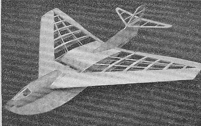
The published plans of his free-flight models were Vultan (Aeromodeller Jan 54), Javalan (Aeromodeller March53) and Sea King (Aeromodeller March 58). By 1958 Laurie Ellis was in Canada where he demonstrated the Sea King to great acclaim. He said that it would be well suited to radio control because of its spacious fuselage and presumably because of the general inconvenience of recovering a free-flight model over water.
Each of these models used a flat bottomed wing section with an upswept trailing edge provided by adjustable control surfaces. The flat base was evidently very convenient for construction. A ‘droop snoot’ and rounded leading edge was made by adding a shaped strip beneath the leading edge on completion of the main structure flat on the building board.
The construction of a delta wing itself can be very light owing to the sparseness of the structure i.e. the empty space within the envelope. Vultan used several swept span wise diaphragms with straight profiles, with chord wise stringers over and beneath. On the other hand both Javelin and Sea King used full depth capped ribs with swept span wise stringers to give the necessary bending strength and stability to the structure. These structures are feasible with low aspect ratio surfaces, where bending loads do not require heavy spars.
The MP115 Design
I had some further experience of delta structural design in my work on the tail-fins of full-size airships and in hybrid airship flying research models. It seems to have been quite a thorough background into some of the design issues faced in creating the MP115 glider and electric ducted fan, radio controlled models. However in many respects there remain unknowns about the stability and control of such slender delta models. The MP115 can be regarded as a very experimental model and I am hoping to learn much from it, probably the hard way.
Although I wanted to capture the style of the HP115 it seemed impractical to make a true scale model because of its extreme leading edge sweep. Therefore the leading edge sweep was reduced to 60 degrees ensuring enough wing area for low wing loading and slow flight. It is probable that the oscillatory type of flight will be avoided with this angle of sweep, although this is at the transition angle above which the vortex flow is known to develop. The drawback of low aspect ratio is the inevitable increase in lift dependent drag, but an advantage is the minimal response to vertical or head gusts of wind. Indeed this was the principle reason for the wing shape chosen for the ill-fated TSR 2 project.
For the MP115 the wing section chosen is the Eppler E182, an 8.6 % thick section with a slightly reflexed trailing edge. This section has a positive nose up and thus stable pitching moment about its quarter chord. Nonetheless the effect of high sweep back is to load up the tips of the wing, with consequent risk of tip stalling. This is dealt with by introducing washout to the tips of the delta, as can be clearly seen in side elevations of the Vulcan bomber. These measures seem to be necessary on a pure delta wing planform, with no tail or fore-plane for stability or for trimming in pitch. The MP115 wing has an overall washout at the tips of four degrees. These measures are intended to avoid the need for excessive built-in elevator angles seen on some model deltas and flying wings.
The sharp leading edge of the original is not retained, to try to avoid any sudden unstable flow effects. However the intention is to permit high angles of attack to be achieved in the slow speed flight regime anticipated for the model, whilst avoiding a sudden stall and spin risks. Development is being undertaken in two forms, firstly as a slope soaring glider landing on its skids and secondly as an electric ducted fan (EDF) machine equipped with an optional fixed tricycle undercarriage, like the HP115.
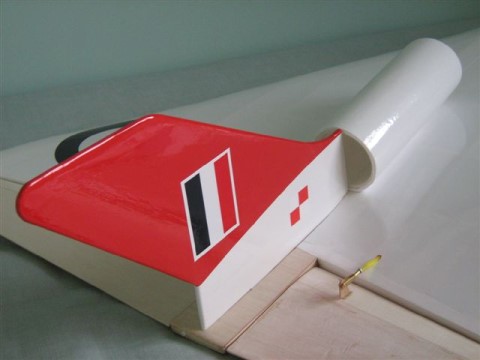
Both model versions use the same wing of aspect ratio 1.65 and a span of 750 mm (30 in). Both models have the side elevation and fin shape of the HP115 to 1/14th scale with its distinctive under slung nose and low cockpit canopy. This latter feature was adopted to avoid flow disturbance into the jet intake. Also it was considered better able to withstand landing accidents should the aircraft overturn. On the powered version, the ducted fan sits on top of the wing, in the dorsal position, thus closely retaining the style of the original. The fin carries a rudder directly in the exhaust of the fan to provide a strong ground steering control.
The wing carries single control surfaces each side, mixed electronically to provide elevator and aileron control functions. The control surfaces are built-up with a solid balsa leading edge and a hollow 1/32nd sheet construction behind, to ensure approximate balance of the surfaces at their hinge lines. The hinge line is set back to minimise control hinge moments, its leading edge being blended in towards the upper surface with an inverted aerofoil section. This was a feature of the original’s aerodynamic design giving priority to upward movement of the elevators thought necessary to induce and sustain the high incidence flight anticipated.
Wing Structure
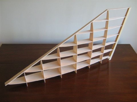
The structure comprises a rectangular gridwork of spars and ribs assembled on the egg-box principle. This does not require any jigging on the bench and in effect the assembly is achieved in space making the two halves separately. Each half can be stood up on its centre-plane to ensure accuracy and alignment with a setsquare. On attaching the swept leading edge, the wing profiles become locked, and the half structures are then joined using the fuselage formers. This wing framework is completed by adding the spar flanges and rib caps together with the leading edge sheeting. The lower fuselage has corner longerons with sheeting over and with spruce skids added at the back and front.
The front fuselage on the glider version is purely a profile shape with a balsa and ply keel, with foam cheeks finished in glass cloth. The nose fuselage is removable to gain access to the battery compartment. The jet shroud structure for the glider is purely a representative dummy in the form of a Depron tube.
On the EDF version the front fuselage is of balsa construction essentially resembling the original shape, and containing the power battery for the EDF. A scale-like nose is formed from foam with a moulded acetate cockpit canopy containing a pilot. The undercarriage is optional and although permanently fixed on the original, its omission on the model saves significant weight and aerodynamic drag. With suitable power the model is capable of taking-off from mown grass sliding on its skids. The tricycle undercarriage is an option fitted, with a castoring nose leg in conjunction with the rudder for ground steering.
Dimensions
Full-Size HP115 Model Glider MP115
Span 20 ft 75 cm (29.5 in)
Length 45 ft 91.4 cm (36 in)
Root chord 36.4 ft 74 cm (29.13 in)
Centre chord 40 ft 77.9 cm (30.67 in)
Aspect Ratio 0.92 1.65
|
